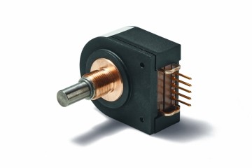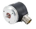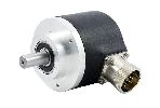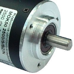
- Different standards for output
- High resolution
- Wide operating temperature range
- A large selection of housing and fixing
- Miniature and industrial executions
- Availability from the warehouse
Application
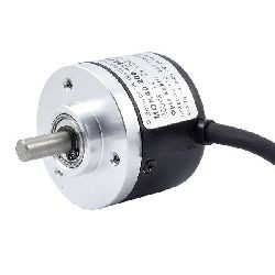
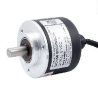
Rotary-pulse transducers are designed to measure angular displacements, and thus for both angular and angular velocity measurements. With the help of belt drive, sprocket or friction wheel, linear movements can also be measured.
Operation
These transducers allow to determine the relative position by counting pulses. In this case, the direction of motion can be recognized by the phase shift of channels A and B so that the cooperating electronics must add or subtract incoming pulses (so-called quadrature). The zero channel C (index) means, at each transmitter turn, an absolute position that can be used to determine the zero position of the measurement system. When synchronizing this signal with the signal from the initiator placed eg at the beginning of the milling table, a precise zero point can be obtained despite the high initiator hysteresis.
Resolution
The resolution of the transducer is determined in plots corresponding to the number of bars on the transducer pitch plate or the number of periods of rectangular wave coming from one transducer channel. The counter distinguishes all edges of rectangular signals, which increases the number of pulses 4 times.
Interface
Impulse transmitters are made in several output standards: the most popular OC enables output operation with a different input voltage from the transmitter supply and is ideal for optoisolation of the measurement system, standard NL with 5V power supply is well suited for high speed, standard PP is willingly used in industrial conditions with PLC devices.

